KXD Steel Technical & Project Team | Progettazione, Dettagliamento e Consegna Progetti | Pubblicato: 27 agosto 2026
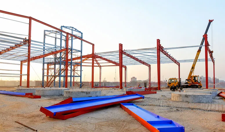
Edificio in acciaio strutturale la costruzione si articola in dieci fasi: definizione dei carichi, progettazione strutturale, approvazione del dettagliamento, approvvigionamento materiali, taglio CNC, saldatura, trattamento superficiale, assemblaggio di prova, imballaggio per esportazione e montaggio in cantiere. Ogni fase produce un documento o un controllo fisico che deve essere superato prima dell'inizio della successiva.
Le descrizioni di processo e i parametri di prodotto riportati di seguito riflettono le capacità KXD e i dati delle schede prodotto aggiornati ad agosto 2026. La sequenza e i punti di ispezione sono personalizzabili in base ai requisiti contrattuali e del paese di destinazione.
Il motivo per cui è necessario esaminare questa sequenza anziché trattare la fabbricazione come una scatola nera è pratico. Per un plant manager, ognuna di queste fasi contiene un punto decisionale in cui una modifica è economica, e un punto poco dopo in cui la stessa modifica diventa costosa. Sapere quale sia l'uno e quale l'altro è ciò che in gran parte distingue un progetto che viene consegnato nei tempi da uno che non lo fa.
Fase 1: Definire il programma dei carichi prima di ogni altra cosa
Un ingegnere strutturale non può iniziare finché i carichi non sono noti, e i carichi su un edificio industriale derivano dal vostro processo produttivo, non da un catalogo.
Cosa raccogliere:
- Capacità del carroponte, luce, numero di carroponti per campata e classe di utilizzo
- Ingombri dei macchinari e carichi di eventuali attrezzature sospese dalla struttura del tetto
- Soppalchi, il loro carico variabile e se sono strutturalmente indipendenti
- Impianti montati sul tetto: HVAC, estrazione polveri, solare
- Vincoli specifici del processo come zone di lavoro a caldo, lavaggio ad alta pressione o atmosfera corrosiva
- Valori di progetto locali per vento, neve e sismicità, ottenuti dall'autorità del paese di destinazione
Output verificabile: un unico documento di programma dei carichi, firmato da chi è responsabile del layout produttivo. Se il responsabile di produzione non l'ha visto, non è completo.
Il fallimento più comune in questa fase è trattare le attrezzature future come fuori dal campo di applicazione. Una gru installata nell'anno quattro modifica comunque i pilastri progettati nell'anno zero.
Fase 2: Progettazione strutturale secondo la normativa corretta
La progettazione inizia una volta fissati il programma dei carichi e la geometria del sito. Due decisioni governano il risultato.
Selezione della normativa. Gli standard di progettazione disponibili nella gamma di prodotti KXD includono GB, ASTM, AISI, JIS, BS, DIN ed EN. La normativa vigente è quella che l'autorità edilizia locale accetterà per il permesso. Specificarla nel contratto, perché una struttura progettata secondo una normativa non può essere certificata retroattivamente secondo un'altra senza ricalcolo.
Grado del materiale. Sezioni H saldate in Q235B e Q355B sono entrambe standard. Q355B ha un limite di snervamento superiore, che consente sezioni più leggere e peso di spedizione inferiore; Q235B costa meno per tonnellata. Su telai industriali con carichi da gru o grandi luci, la riduzione di tonnellaggio favorisce solitamente Q355B.
Il lavoro di progettazione in questa fase viene eseguito tramite Tekla, PKPM e 3D3S, che producono il modello di analisi che successivamente genera direttamente i dati di fabbricazione.
Output verificabile: un rapporto di calcolo strutturale che riporta il codice di progettazione e i valori di vento, neve e sismici utilizzati. Leggere i valori di input. Se non corrispondono ai numeri forniti dal vostro ingegnere locale, fermarsi e risolvere la questione immediatamente.
Fase 3: Dettaglio e gate di approvazione dei disegni
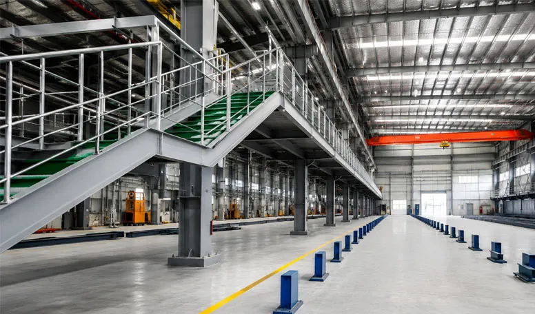
Il dettaglio converte il modello di analisi in disegni di officina: ogni elemento, ogni connessione, ogni foro per bullone, ogni saldatura.
Questo è il gate più difficile da comprendere dal lato dell'acquirente, perché approvare i disegni sembra una pratica burocratica. Non lo è. Una volta che i disegni vengono rilasciati all'officina, l'acciaio viene tagliato sulla base di essi. Le modifiche dopo questo punto significano ritaglio, e l'acciaio ritagliato è scarto.
Cosa controllare effettivamente sui disegni di approvazione:
- Luce netta e altezza di gronda misurate internamente, corrispondenti al vostro layout
- Posizioni di porte e aperture rispetto al vostro flusso di traffico e disposizione delle banchine
- Quota della via di corsa della gru e altezza di libera del gancio rispetto al materiale stoccato o in lavorazione
- Posizioni dei pilastri rispetto agli ingombri dei macchinari, in particolare al perimetro
- Layout dei bulloni di ancoraggio, di cui l'appaltatore civile ha bisogno prima del getto delle fondazioni
Output verificabile: un'approvazione timbrata o scritta del set di disegni esecutivi, con un numero di revisione. Conservare il numero di revisione. Ogni successiva contestazione vi farà riferimento.
Fase 4: Approvvigionamento dei materiali e certificazione di acciaieria
L'acciaio viene ordinato sulla base dei disegni approvati. Ogni colata di acciaio arriva con un certificato di prova dell'acciaieria che riporta la composizione chimica e le proprietà meccaniche.
Output verificabile: certificati di acciaieria che coprono i gradi utilizzati nel vostro edificio, tracciabili al materiale impiegato. Richiedeteli in questa fase piuttosto che alla consegna. Un fornitore che può produrli prontamente sta gestendo la tracciabilità del materiale; uno che non può sta ricostruendo la documentazione in seguito.
Fase 5: Taglio e foratura CNC
I dati di fabbricazione fluiscono dal modello di dettaglio alle attrezzature CNC, che tagliano lamiere e profilati e forano i fori per i bulloni secondo le dimensioni del disegno. Il taglio da dati generati dal modello anziché da dimensioni trascritte manualmente elimina una categoria di errori che in passato dominava i problemi di assemblaggio in cantiere.
Output verificabile: verbali di ispezione dimensionale su componenti tagliati, campionati rispetto al disegno. Su un ordine di grandi dimensioni, chiedere il tasso di campionamento piuttosto che una dichiarazione generica che l'ispezione sia avvenuta.
Fase 6: Assemblaggio e saldatura
Le lamiere tagliate diventano sezioni a H saldate e assemblaggi di collegamenti. La saldatura automatizzata gestisce le lunghe e ripetitive saldature anima-ala; la saldatura manuale copre i collegamenti e le geometrie che la linea automatizzata non può raggiungere.
La saldatura è la fase in cui si determina la qualità e dove è più difficile verificarla successivamente. Due elementi la rendono verificabile:
WPQR. I Welding Procedure Qualification Records documentano che una specifica procedura, su un grado di materiale e un intervallo di spessore specifici, è stata qualificata mediante prova. KXD elenca i WPQR come disponibili su richiesta. Richiedere i documenti che coprono i tipi di giunti e gli spessori presenti nel vostro edificio, non una dichiarazione generica di capacità di saldatura.
Prove non distruttive. Controlli ultrasonici o radiografici su saldature a piena penetrazione, con una frequenza specificata nel contratto. L'ispezione da parte di terzi tramite SGS, Bureau Veritas o Intertek può essere organizzata su richiesta. Si noti che i rapporti di ispezione specifici sono generati per progetto, quindi qualsiasi rapporto mostrato dovrebbe fare riferimento al vostro ordine, non a uno precedente.
Output verificabile: WPQR che coprono i vostri tipi di saldatura, più rapporti NDT che fanno riferimento al vostro progetto.
Fase 7: Sabbiatura e trattamento superficiale
I componenti saldati passano attraverso la sabbiatura per rimuovere la scaglia di laminazione e la ruggine prima del rivestimento. L'adesione del rivestimento dipende quasi interamente da ciò che avviene in questa fase, ed è per questo che il grado di preparazione superficiale deve essere incluso nel contratto insieme alla specifica della verniciatura.
Negli edifici industriali vengono utilizzati due tipi di rivestimento:
Sistemi di verniciatura. Primer più intermedio e finitura, con spessore totale del film secco specificato in micron. Adatti ad atmosfere industriali normali e riparabili in cantiere.
Zincatura a caldo. Rivestimento di zinco applicato per immersione. Durata maggiore in ambienti corrosivi e minore manutenzione, a costo più elevato. Comporta un vincolo fisico che vale la pena conoscere in anticipo: i componenti devono entrare nella vasca di zincatura, il che limita la lunghezza degli elementi e talvolta impone un giunto che un elemento verniciato non richiederebbe.
Per un sito costiero, un processo ad alta umidità o qualsiasi situazione che comporti esposizione chimica, la scelta del rivestimento ha un effetto maggiore sul costo a vent'anni rispetto al progetto del telaio.
Output verificabile: letture dello spessore del film secco, o registrazioni del peso del rivestimento di zincatura, confrontati con i valori specificati.
Fase 8: Assemblaggio di prova e ispezione del prodotto finito
Le sezioni complesse vengono assemblate di prova in officina prima della spedizione. Lo scopo è individuare problemi di accoppiamento dove costano ore invece di trovarli in cantiere dove costano settimane.
Output verificabile: registrazioni dell'ispezione del prodotto finito e, dove si applica l'assemblaggio di prova, fotografie o un rapporto che conferma l'accoppiamento. Per un primo ordine con un nuovo fornitore, un'ispezione pre-spedizione da parte di terzi vale il suo costo.
Fase 9: Marcatura, imballaggio e documentazione di esportazione
Ogni componente è contrassegnato con una marca di pezzo che corrisponde ai disegni di montaggio. Questo è il collegamento tra un container pieno di acciaio e un edificio.
La sequenza di imballaggio ha più importanza di quanto sembri. I componenti dovrebbero essere caricati in modo che ciò che viene montato per primo venga scaricato per primo, e bulloni, piastre di collegamento e parti piccole dovrebbero essere imballati in scatole etichettate che arrivano con i telai a cui appartengono, non in un container successivo separato.
La geometria del container è un vincolo reale sulla lunghezza degli elementi. I container standard da 40 ft ospitano elementi di circa 12 m; elementi più lunghi richiedono flat rack o open top, il che modifica il costo del trasporto e talvolta il progetto del giunto. Se il vostro dettaglio produce elementi da 15 m, l'implicazione sul trasporto dovrebbe essere discussa nella fase di dettaglio, non al momento della prenotazione.
Output verificabile: una lista di imballaggio abbinata alle marche dei pezzi, più il set di documenti di esportazione — fattura commerciale, lista di imballaggio, polizza di carico, certificato di origine e qualsiasi documentazione specifica per la destinazione.
Confermare l'incoterm nella fase contrattuale. FOB, CIF e DAP producono numeri diversi per lo stesso edificio, e collocano le responsabilità di trasporto, assicurazione e sdoganamento in mani diverse.
Fase 10: Accettazione delle fondazioni e montaggio in cantiere
Le fondazioni sono progettate in base alle condizioni del suolo locale e realizzate da un'impresa locale. L'interfaccia tra il loro lavoro e l'acciaio importato è rappresentata dalla disposizione dei tirafondi, e questa interfaccia è il punto in cui si concentrano i ritardi in cantiere.
La sequenza di montaggio:
- Verificare i tirafondi rispetto alla disposizione approvata prima che l'acciaio arrivi in cantiere. Gli errori di tolleranza di posizione individuati ora sono correggibili; individuati dopo il solevamento del primo telaio, non lo sono più.
- Montare la prima campata controventata e verificarne la verticalità e la squadratura. Ogni telaio successivo si riferisce a questo, quindi un errore qui si propaga in tutto l'edificio.
- Installare i telai rimanenti mantenendo il controventamento provvisorio finché quello permanente non è completato. La rimozione anticipata del controventamento provvisorio è una causa comune di incidenti durante il montaggio.
- Montare gli arcarecci e il controventamento permanente, quindi verificare nuovamente la verticalità prima del serraggio finale dei bulloni ad alta resistenza.
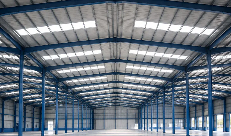
- Installare prima il rivestimento del tetto, poi le pareti. Un tetto impermeabile consente di iniziare i lavori interni mentre prosegue il montaggio delle pareti.
- Montare aperture e accessori: porte, serrande avvolgibili, lucernari, ventilazione, grondaie e pluviali.
- Sopralluogo finale con il supervisore del montaggio, registrando ogni elemento prima della smobilitazione.
Output verificabile: un rilievo as-built che conferma le tolleranze di verticalità e allineamento, più una punch list firmata.
KXD fornisce supporto all'installazione anziché una forza lavoro locale completa nella maggior parte dei progetti export, quindi l'appaltatore di montaggio è tipicamente locale. Confermare per iscritto chi supervisiona, chi fornisce le attrezzature di sollevamento e chi è responsabile della correzione dei problemi di assemblaggio, prima che l'acciaio venga spedito.
La specifica del Custom Steel Structure Building prodotta da questo processo
Le fasi sopra si applicano al prodotto general-purpose prima che venga configurato come officina, magazzino o edificio industriale:
- Telaio principale: sezione H saldata Q235B o Q355B
- Luce libera: fino a 100 m campata singola
- Altezza edificio: 3–30 m
- Pendenza tetto: da 1:10 a 1:5
- Resistenza al vento: fino a 160 km/h, personalizzabile secondo le normative locali
- Rivestimento: acciaio monostrato, EPS, PU, lana di roccia o lana di vetro
- Durata di progetto: oltre 50 anni
- Ordine minimo: 600 m²
- Capacità di fornitura dichiarata: 8.000 tonnellate/mese
- Fascia di prezzo pubblicata: USD 40–100/m², a seconda delle specifiche
Interpretate correttamente il dato sulla capacità. 8.000 tonnellate/mese è una dichiarazione sulla capacità dello stabilimento, non una promessa sulla vostra data di consegna. I tempi di consegna dipendono dal tonnellaggio, dalla complessità dei collegamenti, dal ciclo di rivestimento e dal carico di lavoro attuale dello stabilimento. Fatevi confermare il programma per iscritto in fase d'ordine.
L'MOQ di 600 m² esiste perché i costi fissi delle Fasi 2, 3 e 9 non si riducono proporzionalmente. Le ore di progettazione, la modellazione di dettaglio e la documentazione per l'esportazione costano più o meno lo stesso per un edificio di 400 m² e per uno di 4.000 m².
Dove si inseriscono le certificazioni nella sequenza
La certificazione è più facile da interpretare una volta collocata all'interno delle fasi descritte sopra.
La Commissione Europea dichiara che la marcatura CE per i prodotti da costruzione indica la conformità alle prestazioni dichiarate valutate secondo una norma europea armonizzata o una valutazione tecnica europea, con materiale della Commissione che fa riferimento specifico alla EN 1090 per i prodotti strutturali. La EN 1090 copre l'esecuzione di strutture in acciaio e il controllo di produzione in fabbrica che ne è alla base, il che significa che si applica dalle fasi 5 alla 8. Per una destinazione europea, questo è il certificato che viene verificato in fase di permesso.
ISO identifica la ISO 9001 come la sua norma per i sistemi di gestione della qualità, la ISO 14001 come la sua norma per i sistemi di gestione ambientale e la ISO 45001 come la sua norma per i sistemi di gestione della salute e sicurezza sul lavoro. Queste certificano come viene gestita la fabbrica, non le prestazioni strutturali del vostro edificio.
Per i progetti nordamericani, l'American Institute of Steel Construction (AISC) è l'organismo di riferimento per la certificazione dei fabbricanti, incluse le complesse certificazioni di rivestimento pertinenti alla fase 7.
Rispetto all'acquisto di un edificio modulare a modello fisso attraverso un canale di distribuzione di costruzioni metalliche, questo percorso in dieci fasi richiede più tempo per arrivare a un prezzo definitivo e richiede maggiore input da parte vostra nelle fasi 1 e 3. Ciò che restituisce è una struttura dimensionata in base ai vostri carichi effettivi e una documentazione tracciabile in ogni fase. I modelli di catalogo sono dimensionati per una gamma di condizioni, il che di solito significa pagare per una capacità che l'edificio non utilizzerà mai, e raramente accolgono una gru da 30 t o una luce libera di 60 m.
Due fasi in cui i problemi hanno effettivamente origine
Fase 3, non fase 10. I problemi di assemblaggio in cantiere sono visibili durante il montaggio, quindi è lì che vengono incolpati. La maggior parte di essi è stata creata all'approvazione del dettaglio, quando una dimensione che nessuno ha controllato è andata in officina. Il costo di un'ora spesa nella revisione dei disegni non è paragonabile al costo di un elemento ritagliato nuovamente che arriva sei settimane dopo.
L'interfaccia delle fondazioni della fase 10. Il posizionamento dei bulloni di ancoraggio viene eseguito da un appaltatore locale che lavora da un disegno prodotto a 8.000 km di distanza. Le tolleranze di posizione ed elevazione sono strette e i bulloni annegati non possono essere spostati una volta che il calcestruzzo indurisce. Rilevateli prima che arrivi l'acciaio. Quando vengono riscontrati errori, esistono opzioni di correzione — piastre di base allargate, ancoraggi forati, regolazioni con malta — ma tutte richiedono l'approvazione ingegneristica e tutte richiedono meno tempo quando vengono scoperte prima che la gru sia prenotata.
FAQ
D: Quanto tempo richiede l'intero processo dall'ordine all'edificio eretto?
R: Varia in base al tonnellaggio, alla complessità delle connessioni e al percorso di rivestimento, e la tratta di spedizione dipende dalla destinazione. Non è possibile fornire una cifra responsabile senza questi input. Richiedete un programma fase per fase alla conferma dell'ordine, che mostri separatamente le finestre di approvazione del dettaglio, fabbricazione, spedizione e montaggio.
D: In quale fase posso ancora modificare il progetto senza costi?
R: Liberamente fino alla Fase 2, a costo di ricalcolo durante la Fase 3, e a costo del materiale dopo che i disegni sono stati rilasciati allo stabilimento nella Fase 5. Le modifiche dopo il taglio si traducono in scarto.
D: Chi è responsabile delle fondazioni?
R: L'acquirente, tramite un contraente locale. Il produttore fornisce gli schemi dei tirafondi e le reazioni; le condizioni del terreno locale determinano il progetto delle fondazioni, motivo per cui vengono commissionate a livello locale.
D: Posso avere un'ispezione di terze parti durante la fabbricazione?
R: Sì. SGS, Bureau Veritas e Intertek sono disponibili come opzioni di collaudo di terze parti su richiesta. Specificare i punti di ispezione e i punti di sospensione nel contratto, perché un'ispezione che nessuno ha programmato non avrà luogo.
D: Quali documenti dovrebbero arrivare con la spedizione?
R: Lista di imballaggio abbinata ai contrassegni dei pezzi, disegni di montaggio, certificati di fonderia, registri di saldatura e NDT, registri dello spessore del rivestimento e il set di documenti di esportazione. Richiedere il fascicolo tecnico come deliverable nel contratto, non come favore al momento della spedizione.
D: La zincatura modifica il progetto?
R: Può farlo. Gli elementi devono entrare nella vasca di zincatura, il che pone un limite alla lunghezza dei componenti e può richiedere una giunzione che un elemento verniciato non necessiterebbe. Sollevare la decisione sul rivestimento alla Fase 2, prima che i dettagli fissino le lunghezze degli elementi.
L'autore
Il KXD Steel Il Team Tecnico e di Progetto comprende più di 100 ingegneri senior e professionisti tecnici, insieme a oltre 50 progettisti, architetti, disegnatori tecnici e consulenti. Il team gestisce la progettazione, i dettagli, la fabbricazione e la consegna di strutture in acciaio prefabbricate per applicazioni industriali, commerciali, logistiche, agricole e infrastrutturali, con esperienza di progetto e di mercato in oltre 80 paesi e regioni. L'ingegneria interna utilizza Tekla, PKPM e 3D3S; la produzione comprende taglio CNC, saldatura automatizzata, sabbiatura, trattamento superficiale, assemblaggio dei componenti e ispezione del prodotto finito.


 27 agosto 2026